Preface
The SDP3x differential pressure sensor features excellent accuracy and long-term stability and has no zero-point drift. It is the perfect choice for high volume and cost-sensitive applications, where small size is essential. This application note gives advice and guidelines for engineers integrating an SDP3x sensor into their product, to make sure that the sensor can unfold its full performance after being placed in an application.
Introduction
The world’s smallest differential pressure sensor SDP3x measures only 5mm x 8mm x 5mm, opening up new dimensions of integration and application possibilities. The sensor is based on the next generation of the CMOSens® chip, which is the heart of Sensirion’s new sensor platform for measuring differential pressure and mass flow. The small size offers new prospects for applications with differential pressure sensors. To ensure best performance it is important that a few simple recommendations are taken into account when designing a product using SDP3x. This
application note will give advice about how to design the manifold or flow channel in order to ensure a tight but stress-free connection with the sensor.
Sensor Connection
The sensor can be reflow soldered to a printed circuit board (PCB). Soldering guidelines and pin assignments can be found in the sensor’s datasheet. The three pins in the corners of the sensor will ensure correct placement on the PCB.
For the pressure connections there are various options:
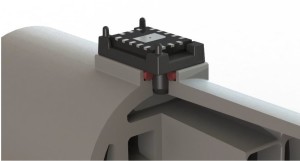
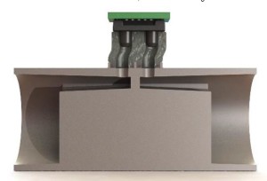
- The sensor can be directly connected to a flow channel, manifold or gas chambers using radial or axial sealing.
- A soft adaptor piece made of silicone or a similar material can be used to connect the sensor to the manifold.
Such an adaptor piece can serve as a seal between sensor and manifold as well as ensure a flexible connection
between the two to provide stress relief.
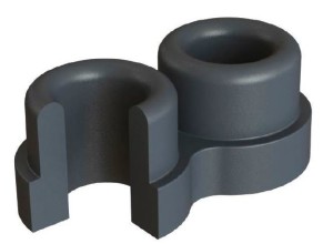
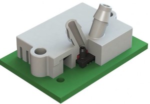
- A hard adaptor piece may be used to connect to the sensor. This will add an additional component, but can help
simplify the assembly process. Ask Sensirion for a suitable design of the sensor-side part of the adaptor or the
availability of an off-the-shelf adaptor. Such an adaptor piece can be designed to fit a manifold or to allow tubes
being used to connect to the sensor.
Tubing
The SDP3x is not designed to be used directly with tubes. Where tube connections are necessary, Sensirion
recommends using an adaptor piece (see above) or the use of other sensors with long ports from Sensirion’s
differential pressure portfolio.
Where tubes need to be used for sensor testing or during the product design phase, it is important to keep them as
short as possible (below 10 cm) and make sure to read the Application Note “Pressure drop in hose” in order to
calculate the measurement deviation caused by the tube.
Sealing
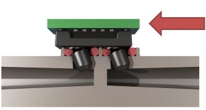
The sealing can either be done radially, axially or by means of a gasket.
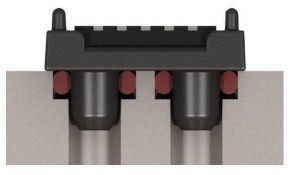
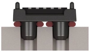
- For radial sealing two O-rings need to ensure a gas tight connection between the sensor and the flow element.
Recommended O-ring dimensions are: ID=2mm, OD=4mm, cross section: 1mm. The inner diameter of the
groove should be 3.4mm.
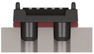
- In case of axial sealing it is important to ensure a constant but not excessive contact pressure to guarantee a
tight connection without mechanical stress on the sensor. In case of axial sealing a soft sealing material is
recommended.For gasket sealing a flat soft sealing material is punched to fit the sensor when placed on top of the sensor
surface.
- Sealing can also be done by a soft injection-molded “sealing adaptor” that connects the sensor with the manifold.
Such a design can help reduce mechanical stress on the sensor.
Stress-relief
The SDP3x is a robust component. Although the soldering pad design is fully sufficient to fulfil its purpose as a device
fixation, special care needs to be taken since other mechanical parts are connected to the ports of the sensor and
therefore might induce peak stress to the sensor, e.g. when the device falls to the ground.
There are different ways to prevent excessive stress:
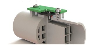
- The manifold or main flow channel is fastened to the PCB. This can be achieved by clip-in pins, gluing or
screwing the PCB to the manifold. With the sensor and the flow guide being firmly attached to the board, shear
forces can be absorbed
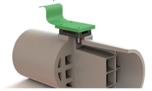
- The PCB print is ONLY firmly attached to the sensor and is electrically connected via flex-prints or cables.
Because the PCB can move freely, no stress-relief between the sensor and the flow element is needed.
- The pressure ports of the main flow channel are soft and can bend (flexible manifold material). There is no
mechanical stress on the pressure ports. This can be achieved in conjunction with a sealing method, where part
or the whole flow manifold is made of a soft, flexible and sealing material. - Important: Avoid a situation where the PCB is rigidly mounted to the case of the application and the sensor is rigidlyconnected to the flow channel, but there is no stress-relief between the flow channel and the PCB.
